A detailed understanding of the different fueling modes and how they are calculated is necessary to tune them effectively. If you do not understand all of the fueling calculations, tuning EE is very error prone.
Contents
Speed Density
Speed density operation takes effect when the MAF sensor is disconnected or faulty. It can also be used as a primary metering method, which has several advantages, including improved throttle response and simpler intake plumbing.
During speed density operation, the MAP pressure of the incoming air (density), and engine RPM (speed) are referenced against the VE (Volumetric Efficiency) table to estimate airflow.
This system is incredibly accurate, assuming the VE table is an accurate representation of the efficiency of the engine. If the engine is modified, the VE table must also be modified for speed density mode to function correctly.
MAF
In MAF (mass air flow) mode, a sensor in the intake tract using a series of heated wires attempts to directly measure airflow.
The sensor emits a signal which is compared to a table containing calibrations for the sensor to determine airflow grams per second (AFGS).
Although the calibration is not as sensitive to changes in engine design as speed density’s VE table, it is still slightly sensitive to changes to the intake tract design, as well as the regularity of the incoming air, which can be affected by camshafts with higher than normal overlap, causing a back-and-forth motion of air across the sensor wires.
Open Loop Operation
This simple control mode takes effect when the car is too cold for the oxygen sensors to work, if they are providing an unreliable signal, or if the engine is operating in a range where the oxygen sensors cannot be trusted.
An open loop control system makes calculations and actuates the controls without having any knowldge of how accurate its calculations will be.
In open loop control mode, EE will use the selected MAF or Speed Density mode for the airflow calculation. It will then calculate the amount of fuel required by the Open Loop AFR Target table, as well as the individual cylinder trims, and fire the injectors.
Closed Loop Operation
In closed loop operation, feedback from the narrow band oxygen sensors is used in an attempt to adjust the air/fuel ratio to 14.7:1, which theoretically provides optimal fuel economy and emissions.
Various conditions must be met before closed loop takes effect, including a time after startup, o2 readyness calculations, and coolant temperature.
Closed loop operation with narrowband sensors limits target air fuel ratios, as they can only provide accurate calculations in a very narrow band around 14.7:1, although some adjustment is possible through alterations in the intended voltage target.
After intial airflow calculation is made using the chosen MAF or Speed Density mode, fuel is calculated at a best-guess to hit a 14.7:1 ratio, then ‘trimmed’ using a variety of methods.
EE uses a three part system to make these adjustments as reliable and as fast as possible:
CORRCL mode works almost independantly of the rest of the closed loop system. It attempts to make small instanenous corrections to the AFR, a ‘fast fine adjustment’.
A ‘voltage error’ as the o2 sensor swings back and forth is filtered, scaled, and turned into a small adjustment, which attempts to make the AFR climb and rise a very small amount near the o2 swing voltage.
For example, an o2 voltage of 300mv indicates a slightly lean air/fuel ratio, so CORRCL might increase fuel ever so slightly. If tuned well, this increase may land around 550mv, at which point the mixture is leaned out even more slightly, landing around 450mv, and so forth, until it gets closer and closer to 500mv.
Although maintaining constant 500mv is nearly impossible, the idea is to make the adjustments smaller and smaller until it makes a very small wave of adjustments near the target.
The effect of CORRCL is not directly visible in logs, and it would be useless if it did, since the corrections are made much too quickly for a datastream to record. It can be determined indirectly through the behavior of the integrator if the changes are positive, which becomes more stable when CORRCL is tuned properly.
INT – The Integrator
The integrator (or short term fuel trim) stores two variables in memory, with 256 possible values each, representing adjustments to the air fuel ratio. The median value of 128 is considered optimal. Values lower than 128 represent fuel being removed (a correction for a rich mixture), and values above represent fuel being added (a correction for a lean mixture).
The adjustments of the integrator are fairly coarse when compared to CORRCL. It attempts to correct larger errors in overall fueling by remembering the last fuel correction and attempting to improve on it.
After a correction is made, the integrator pauses itself for a short time. The length of this time corresponds to how long the new fuel mixture will take to reach the oxygen sensor. This varies depending on engine airflow, as at higher airflows, the changes will propogate much more quickly. This is referred to as the INT Delay.
BLM – Block Learn Mode
As it takes some amount of time for the integrator to make the coarse corrections necessary, it would be a waste to discard those corrections, but it would also be a terrible idea to continue to use them every time the engine operation conditions change.
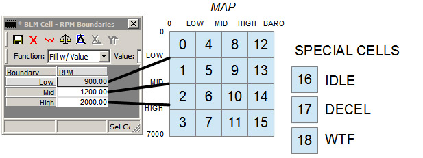
The operating ranges of the engine are divided up into a group of 19 cells (numbered 0-18), each having a particular range of manifold pressure and RPM, so they can represent a range of engine operating. Each cell contains a single number, similar to the integrator – 128 being perfect, lower subtracting fuel, and higher adding fuel.
As the integrator makes changes, these changes are averaged into the BLM cells. When the boundary into another cell is crossed, the integrator is reset using the stored value in that BLM cell, so it can continue to adjust where it left off.
When the car is powered off, BLM values higher than 128 are remembered, but values lower are discarded (this behavior can be modified.). This allows lean conditions to remain corrected between restarts, avoiding lean engine damage.
The LT1 has three “Special” BLM cells, 16-18. 16 is used purely for stopped idling, 17 for decel, 18 for various other conditions, including some states of EGR operation.
PE (Power Enrichment)
As discussed above, the normal operating range of closed loop tends to be around 14.7:1 air fuel ratio while using ordinary gasoline. This provides fairly optimal emissions and power, and corrects for engine wear and a diverse range of operating conditions using oxygen sensor feedback during normal driving conditions.
When maximum acceleration is desired, a 14.7:1 air fuel ratio is no longer optimal, emissions are no longer a concern, and the oxygen sensors can no longer be trusted to provide accurate feedback in that operating range.
PE mode uses a set of tables that add a percentage of fuel to the base fueling calcs of 14.7:1 to achieve a richer mixture.
Power enrichment, as it does not use the oxygen sensors, does not operate in closed loop. However, this mode is special on the LT1, as it does use the block learn mode memory for its base fueling calculation.
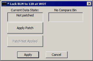
PE calculations begin by trusting 14.7:1 to be whatever the BLM value in the cell you just happen to be in, but by default this only takes effect if the value is higher than 128, meaning the engine was running lean. This is a safety mechanism, as a lean condition during PE may be dangerous.
There is a patch to work around this called a BLM locker, which locks the BLM to 128 whenever PE is entered, ensuring your calculations are fully “open loop”.